「Pylith」Simple tutorial (II) Model set up

1.Trelis interface

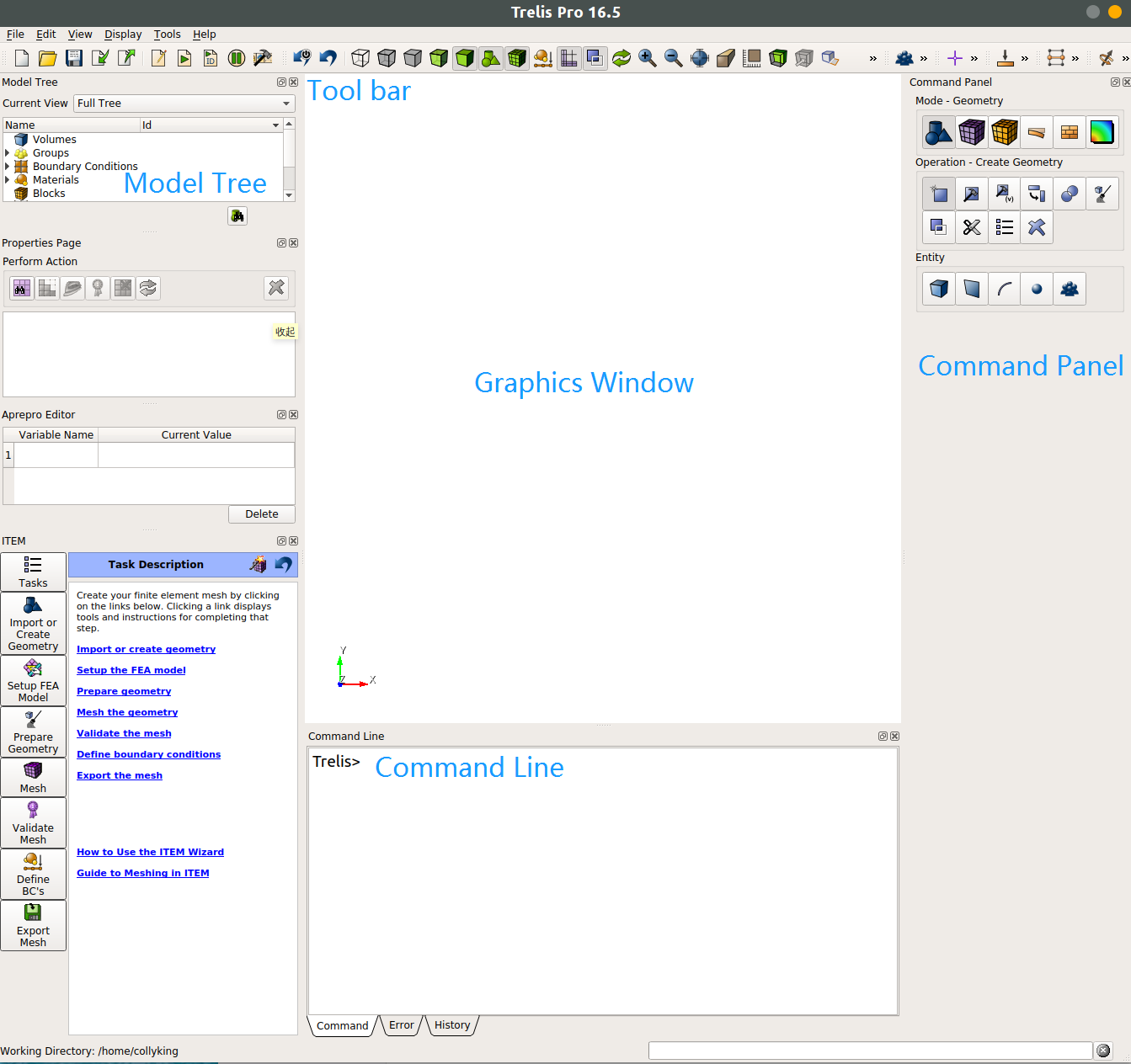
The Trelis software interface is shown below.

00

Panels that are frequently used::

  1. Command Panel: For quick geometry creation, segmentation, combination and mesh division
  2. Command Line: Complete the same function as command panel but by the way of the command lines.
  3. Tool bar: The first five lines are create, open, save, import and export files. The middle part includes running the journal script file and adjusting the observation mode.
  4. Model Tree: Each part of the model is displayed at the level of body-volume-surface-curve-vertex. And each element has a corresponding ID number for designation.
    More details can be found in Official Guide. Note that each step of Trelis has a corresponding script command, which is convenient for saving and sharing.

2.Create Geometry

2.1. Create a volume

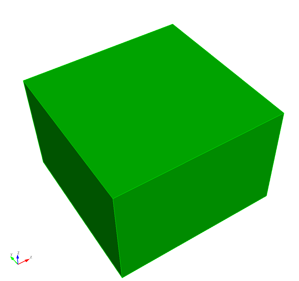
First create a 600km x 600km x 400km volume. Since the default origin is in the center of the new volume, we will move the volume down by 200km. Thus the upside surface represents the surface.
The following script can be copied and pasted directly to the command line.

1
2
3
4
5
6
7
8
9
10
11
12
13
# Like shell script,Trelis uses '#' for comments# ----------------------------------------------------------------------
# Create block
# ----------------------------------------------------------------------

# Block is 600 km x 600 km x 400 km
# -300 km <= x <= 300 km
# -300 km <= y <= 300 km
# -400 km <= z <= 0 km
reset
brick x 600000 y 600000 z 400000

# Translate block so the top is at z=0
volume 1 move x 0 y 0 z -200000

In addition to the above method, Trelis can also create a volume by:

creating vertexes–> creating surfaces by specified vertex–>create a volume by specify surfaces
Although it is more cumbersome, an example also shows here for reference.

1
2
3
4
5
6
7
8
9
10
11
12
13
14
15
16
17
18
19
20
21
22
23
24
25
26
27
28
29
30
31
32
33
34
35
36
37
38
39
40
41
42
43
44
45
46
47
48
49
50
51
52
53
54
# ----------------------------------------------------------------------
# Set units to SI.
# ----------------------------------------------------------------------
${Units('si')}
# ----------------------------------------------------------------------
# Create vertex
# ----------------------------------------------------------------------
# A cuboid has 8 corner points
reset
create vertex { 300*km} { 300*km} { 0*km}
create vertex { 300*km} {-300*km} { 0*km}
create vertex {-300*km} {-300*km} { 0*km}
create vertex {-300*km} { 300*km} { 0*km}
create vertex { 300*km} { 300*km} {-400*km}
create vertex { 300*km} {-300*km} {-400*km}
create vertex {-300*km} {-300*km} {-400*km}
create vertex {-300*km} { 300*km} {-400*km}
# ----------------------------------------------------------------------
# Create curve
# ----------------------------------------------------------------------
# 8 corner points connected to 12 side lines
# top 4 lines
create curve vertex 1 2
create curve vertex 2 3
create curve vertex 3 4
create curve vertex 4 1
# four bottom lines
create curve vertex 5 6
create curve vertex 6 7
create curve vertex 7 8
create curve vertex 8 5
# four side lines (note that the id number of the element in the process of creating a new geometry may also change, so we can give names to important elements.)
create curve vertex 1 5
create curve vertex 6 9
create curve vertex 7 10
create curve vertex 11 15
# ----------------------------------------------------------------------
# Create surface
# ----------------------------------------------------------------------
# 12 lines connected to 6 surfaces
# Top surface
create surface curve 1 2 3 4
# Bottom surface
create surface curve 5 6 7 8
# Side surfaces
create surface curve 1 5 9 10
create surface curve 2 6 10 11
create surface curve 3 7 11 12
create surface curve 4 8 9 12
# ----------------------------------------------------------------------
# Create volume
# ----------------------------------------------------------------------
# Create the volume
create volume surface 1 2 3 4 5 6

The results of the above two ways are exactly the same. For more complicated examples, you can choose your own way according to the situation. Note that if you use the second method to establish the geometry, the id number of most elements will change for the left part of this manual.

2.2. Split the cuboid into two parts

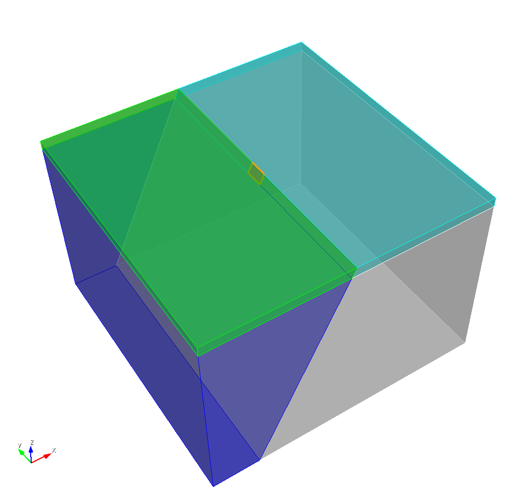
Here we create a plane to divide the cuboid into a upper part as the elastic layer and a lower part as the viscoelastic layer. And a fault plane will be created for simulation.

1
2
3
4
5
6
7
8
9
10
11
12
13
14
15
16
17
18
19
20
21
22
23
24
25
26
27
28
29
30
31
32
# ----------------------------------------------------------------------
# Create interface surfaces
# ----------------------------------------------------------------------
create vertex 0 -300000 0
create vertex 0 300000 0
create vertex -200000 0 -400000
create planar surface with plane vertex 9 10 11
surface 7 name "fault_surface"
delete vertex 9 10 11
create planar surface with plane zplane offset -20000
surface 8 name "material_interface"

# ----------------------------------------------------------------------
# Divide volumes using interface surfaces
# ----------------------------------------------------------------------

webcut volume 1 with plane surface fault_surface
webcut volume 1 with plane surface material_interface
webcut volume 4 with plane surface material_interface
volume 1 name "elastic_xpos"
volume 4 name "elastic_xneg"
volume 5 name "visco_xpos"
volume 6 name "visco_xneg"
# ----------------------------------------------------------------------
# create fault_plane
# ----------------------------------------------------------------------
create planar surface with plane yplane offset -20000
create planar surface with plane yplane offset 20000
split surface 22 with surface 39
split surface 42 with surface 40
surface 43 name "fault_plane"
delete body 2 3 7 8

A more detailed segmentation process can be found in the official tutorial . (A proper vpn tool is required)

2.3. imprint & merge

After creating the split the volume, the points and lines of each sub volumes are probably not the same, so they need to be merged, which takes a certain amount of time under complex geometry.

1
2
3
4
5
# ----------------------------------------------------------------------
# Imprint all volumes, merging surfaces
# ----------------------------------------------------------------------
imprint all with volume all
merge all

3.Meshing

We need to specify the size of each curve, surface or volume before meshing them. And the map meshing scheme is set by default. You can use the command panal or type help volume scheme in the command line to view all the possible meshing schemes. The tetmesh scheme is applied in this example.

1
2
3
4
5
6
7
8
9
10
11
12
volume all scheme tetmesh 
curve all scheme default
# ----------------------------------------------------------------------
# Set discretization size
# ----------------------------------------------------------------------
surface 43 size 1000
volume all size 100000
# ----------------------------------------------------------------------
# Generate the mesh
# ----------------------------------------------------------------------
volume all scheme tetmesh proximity layers off geometric sizing on
mesh volume all

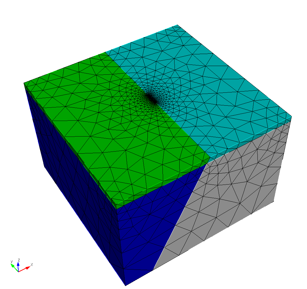
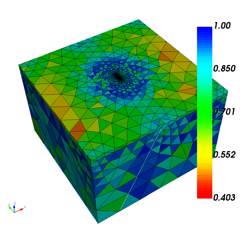
Now the mesh part has completed, and we recommend you to do mesh QA. You can use the command panal or type

1
quality volume all shape global draw mesh

in the command line to do mesh QA.Generally the minimum value should be greater than 0.2 for a reliable Pylith calculation.

The mesh quality of this example is as follows

4.Declare each block and the boundary surfaces

Then we need to declare each block and the bounding surfaces for calculations and determining the boundary conditions of Pylith.

1
2
3
4
5
6
7
8
9
10
11
12
13
14
15
16
17
18
19
20
21
22
23
24
25
26
27
28
29
30
31
32
33
34
35
36
37
38
39
40
41
42
43
44
45
46
47
48
49
50
51
52
53
54
55
56
57
58
59
60
61
62
63
64
65
66
67
68
69
70
71
72
73
74
75
76
77
78
79
80
81
# ----------------------------------------------------------------------
# Create blocks for materials
# ----------------------------------------------------------------------
block 1 volume 1 4
block 1 name "elastic"
block 2 volume 5 6
block 2 name "viscoelastic"

# ----------------------------------------------------------------------
# Create nodeset for fault
# ----------------------------------------------------------------------
group "fault" add node in fault_plane
nodeset 10 group fault
nodeset 10 name "fault"

# ----------------------------------------------------------------------
# Create sideset for faces in fault
# ----------------------------------------------------------------------
group "fault_faces" add face in fault_plane
sideset 10 group fault_faces
sideset 10 name "fault_faces"

# ----------------------------------------------------------------------
# Create nodeset for -x face
# ----------------------------------------------------------------------
group "face_xpos" add node in surface 20
group "face_xpos" add node in surface 28
nodeset 11 group face_xpos
nodeset 11 name "face_xpos"

# ----------------------------------------------------------------------
# Create nodeset for +x face
# ----------------------------------------------------------------------
group "face_xneg" add node in surface 30
group "face_xneg" add node in surface 38
nodeset 12 group face_xneg
nodeset 12 name "face_xneg"

# ----------------------------------------------------------------------
# Create nodeset for +y face
# ----------------------------------------------------------------------
group "face_ypos" add node in surface 21
group "face_ypos" add node in surface 27
group "face_ypos" add node in surface 33
group "face_ypos" add node in surface 35
nodeset 13 group face_ypos
nodeset 13 name "face_ypos"

# ----------------------------------------------------------------------
# Create nodeset for -y face
# ----------------------------------------------------------------------
group "face_yneg" add node in surface 23
group "face_yneg" add node in surface 25
group "face_yneg" add node in surface 31
group "face_yneg" add node in surface 37
nodeset 14 group face_yneg
nodeset 14 name "face_yneg"

# ----------------------------------------------------------------------
# Create nodeset for -z face
# ----------------------------------------------------------------------
group "face_zneg" add node in surface 12
group "face_zneg" add node in surface 16
nodeset 15 group face_zneg
nodeset 15 name "face_zneg"

# ----------------------------------------------------------------------
# Create nodeset for -z face w/o fault
# ----------------------------------------------------------------------
group "face_zneg_nofault" add node in face_zneg
group "face_zneg_nofault" remove node in fault
nodeset 16 group face_zneg_nofault
nodeset 16 name "face_zneg_nofault"

# ----------------------------------------------------------------------
# Create nodeset for +z face
# ----------------------------------------------------------------------
group "face_zpos" add node in surface 10
group "face_zpos" add node in surface 17
nodeset 17 group face_zpos
nodeset 17 name "face_zpos"

5. Export the mesh file

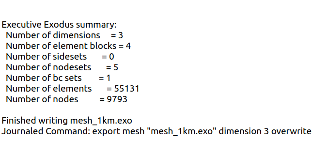
At this point, we only need to exported the mesh file in exo format.

1
2
3
4
# ----------------------------------------------------------------------
# Export exodus file
# ----------------------------------------------------------------------
export mesh "mesh_1km.exo" dimension 3 overwrite

From the output of the Command Line you can see how many elements and nodes you have in the generated mesh file. Generally speaking, the more nodes, the longer the calculation time.


Reference
[1] Aagaard, B.T., Kientz, S., Knepley, M.G., Strand, L., Williams, C., 2017. PyLith User Manual: version 2.2.1. Davis: California: Computational Infrastructure of Geodynamics
[2] Tutorial of Trelis